Contents
Index
Join Parcel
This program allows the user to join parcels together on the graphics screen by using the mouse to identify common points.
In this way a cadastral network is built up, and this can form the basis of a cadastral database.
The parcel that has been selected to be joined is shown on the right side of the screen with the corner points on it circled in red.
The parcel can be dragged with the mouse by locking on to the lot number.
After the first two points in a parcel have been linked, the parcel will be rotated to the same orientation as the network.
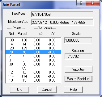
The dialog box on the right of the screen displays information about the points and lines selected for joining.
The normal zoom and pan functions operate and the dialogue box can be moved with the mouse.
If there is a problem with the data for a parcel, or if connections need to be added, the 'Edit Lines' option
can be used to view and/or edit the parcel data. See Edit Parcel The operator will be presented
with the parcel entry screen to edit the parcel.
Lot/Plan
This field show’s the lot number/name and the plan name for the parcel that is to be joined.
Auto Join
The auto-join function will automatically match points on the parcel and the network. It will also determine
line points where applicable. To perform the auto-join, the system requires a co-ordinate or at least one joint point.
If the parcel has a co-ordinate entered, the auto-join facility will automatically match common points and
join it to the network. If you have joined one pair of points and use auto-join, the program will assume the same
azimuth and try to fit the parcel to the network. If two or more pairs are joined, the azimuth can be computed and
the auto-join performed.
When all common points and line points have been selected, click the 'OK' button on the join dialogue box and the
parcel will be displayed in the proposed position on the network. After a parcel has been joined, the point numbers
for that parcel are modified so that the point numbers correspond with the point numbers used in the network,
and the join flag is set..
Joining
The parcel-joining phase requires an operator with some knowledge about the cadastre, and survey plans in general.
The key to efficient joining is to plan the data input, and have quick access to each source document.
It is best to work in blocks of about 500 parcels, and choose the boundary of each area to be as compact as possible.
Long thin areas may have problems in the adjustment phase.
Points are linked by clicking the mouse on each pair of points, as each pair of points is entered,
the system displays 'First Point', 'Second Point' as required.
The points can be in any order; the first can be on the network and the second on the new parcel or vice versa.
When the parcel has a curved side, join the centre points as well so that the joined parcels share the same centre point.
To join points, select the first point in the main window, then select the second point in the parcel window.
As points are selected, they will be highlighted with a square box.
The points in the main window will also show the point number.
A point can also be fitted to a line. To do this, select a point first, then select the line on the other screen.
If you click on a line away from the corner point, the program will assume that a line is required.
The program will compute the position of the point on the line and will indicate the point by a triangle.
This line point will be used during the adjustment phase.
Line points are added to the parcel definition and are also added into the lot string definition as a separate point.
A line point cannot be entered as the first point. If a line point is entered as the second point,
the first point should be on the same line.
The operator can accept the result, or reject it and try other points for the join
Scale
The starting plan will determine the initial scale for the joined block and it is better to start with a recent
reliable survey near the centre of interest or a group of plans which are all similar in date,
and /or were produced by one surveyor. Expand out from the initial parcel in a methodical fashion.
The adjusted values are used to compute transformation parameters for joining in the parcel.
Rotation
This field show’s the rotation the lot has undergone to align it with the group of joined parcels.
Residuals
As each parcel is selected for joining, the surround is closed, and adjusted by “Bowditch’.
The transformation parameters are computed between the local coordinate system of the parcel and the
coordinate system of the network by a “least squares” procedure and the residuals after transformation of
each join point are displayed in the dialogue box.
If the residuals increase as parcels are added,
carry out an adjustment to isolate any problem lines, rather than continue to build on unstable framework.
At the completion of a session, each joined parcel is marked as 'JOINED' in the parcel file,
and its point numbers are altered to match those used in the network.
Pan to Residual
This option will move the screen view to show the points in the selected residual.